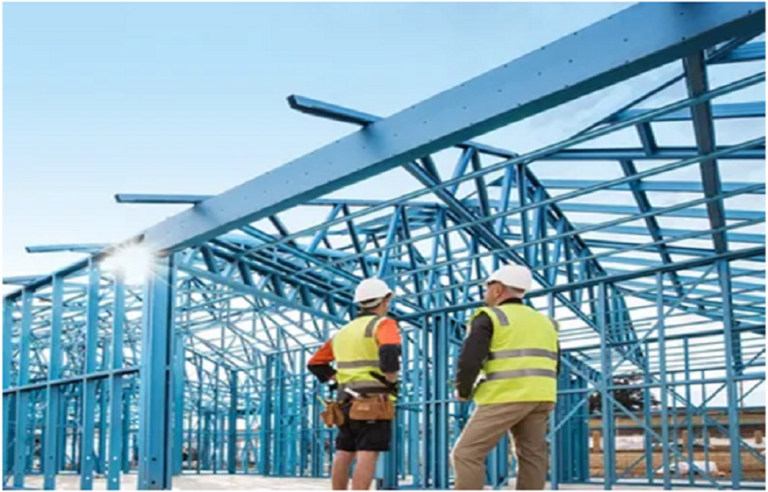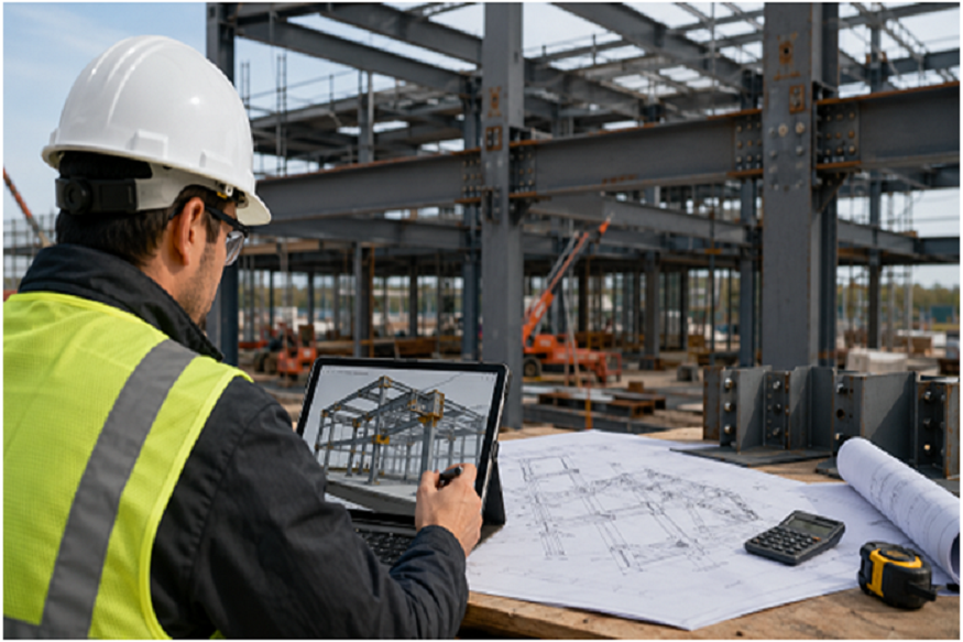
Structural steel gives designers the ability to create strong frames, long spans, industrial facilities, commercial buildings, warehouses, and many other structures. However, steel members do not arrive on a project site ready to assemble automatically. Fabricators need precise information that tells them how each beam, column, brace, plate, bolt, and connection component fits into the overall structure. I believe steel construction succeeds when engineering intent turns into clear fabrication information. Even a small dimensional problem can create trouble during erection because steel components need to fit together within controlled tolerances. Therefore, detailed coordination before fabrication can protect both the schedule and construction quality.
Turning Structural Design Into Fabrication Information
I view structural steel detailing services as an important connection between the engineer’s structural design and the fabricator’s production process. The engineer defines the structural system and design requirements, while the detailer develops the drawings and information needed to fabricate and erect individual steel components. As a result, the project team gains a more practical representation of how the frame will be manufactured and assembled. Steel detailing can include shop drawings for individual members as well as erection drawings that show where those members belong in the structure. In addition, detailed drawings can identify dimensions, holes, plates, bolts, weld information, member marks, and other fabrication requirements.
Key Takeaways
- Steel detailing translates engineering requirements into practical fabrication information.
- Accurate coordination helps reduce fabrication mistakes and erection problems.
- Digital modeling can improve the review of steel connections and relationships with other building systems.
Why Precision Matters in Steel Construction
Steel components are usually fabricated away from the construction site. That means workers cut, drill, weld, and assemble material before the pieces arrive for erection. Therefore, inaccurate information can become expensive. For example, if a connection plate contains holes in the wrong location, the member may not fit during erection. Likewise, an incorrect beam length can affect surrounding steel. Field modification may sometimes solve the issue. However, it can also delay work and require additional engineering review. Therefore, I prefer to resolve dimensional questions before fabrication begins whenever possible.
Read More: How Structural Steel Detailing Supports Safer and More Efficient Construction
Shop Drawings Guide the Fabrication Team
Steel shop drawings focus on individual components. They can show a beam, column, brace, stair component, plate, or other fabricated item in greater detail than general structural drawings. The fabricator can then use that information to prepare the member. I find shop drawings especially important because fabrication requires exact dimensions. Workers need to know where holes belong, where plates connect, and how components should be oriented. Furthermore, member marks help connect each fabricated piece with its location in the building. As a result, the shop drawing becomes an important production document.
Erection Drawings Support Site Assembly
Once fabricated steel reaches the project site, erection crews need to know where each piece belongs. Erection drawings provide that broader view. They can show grids, levels, member marks, orientations, and relationships between structural components. Therefore, erectors can identify the correct sequence and location for installation. Clear erection information becomes especially important on projects with many similar members. Without strong identification, crews may spend more time sorting material. Consequently, good drawing organization can support faster installation.
Connections Require Careful Attention
Connections are among the most important parts of a structural steel frame. They transfer forces between beams, columns, braces, and other components. Therefore, their detailing must follow the structural design and project requirements. A connection may include plates, angles, bolts, welds, stiffeners, or other elements. In addition, connection geometry must fit within the available space. I believe detailed modeling can make complex connections easier to review. A flat drawing may show the required parts. However, a 3D model can make clearance problems more visible.
Coordination With Architectural Elements
Structural steel must support the building while also fitting within the architectural design. For example, columns may sit inside walls. Beams may pass above ceilings. Steel around stair openings must coordinate with architectural dimensions. Likewise, façade systems may attach to structural framing. Therefore, steel information cannot develop in complete isolation. I like to compare structural geometry with architectural requirements early. If a beam conflicts with a ceiling height, the team should identify that problem before fabrication. As a result, designers have more options for solving it.
Coordination With Mechanical and Electrical Systems
Mechanical, electrical, plumbing, and fire-protection systems also compete for space around structural steel. Ducts may need to cross beam zones. Pipes may pass close to columns. Cable trays and equipment supports may require additional framing. Therefore, multidisciplinary coordination becomes important. A coordinated digital model can help teams see these relationships. Through broader BIM services, project teams can review structural components within a more complete building environment, which can support earlier identification of clashes and difficult installation conditions. Consequently, teams can make coordinated decisions before steel fabrication reaches an advanced stage.
Member Marking Improves Organization
Large steel projects may contain hundreds or thousands of fabricated components. Therefore, every piece needs clear identification. Member marks connect each physical steel component with its drawings and erection location. For example, a beam mark may appear on the shop drawing, fabrication tag, delivery list, and erection drawing. This system helps crews track material. In addition, it reduces confusion when several components look similar. I believe good marking and drawing organization become even more important as project size increases.
Material Lists Help Production Planning
Fabricators need to understand the quantity and type of material required. Therefore, detailed steel information can support material lists and production planning. For example, the fabrication team can review member sizes, plate quantities, and connection components. This information helps the shop order raw material and plan cutting. Moreover, accurate planning can reduce unnecessary waste. Steel optimization depends on many factors, including available stock lengths and fabrication methods. Nevertheless, reliable detailing information gives the fabrication team a better starting point.
Fabrication Sequence Affects the Project Schedule
Steel construction often follows a planned erection sequence. Therefore, fabrication and delivery should support that same order. If the erection crew needs the first-floor columns but the fabrication shop delivers upper-level beams first, the site may struggle with storage and schedule control. Detailed production information can help organize fabrication packages. For example, teams may group steel by erection zone, level, or sequence. As a result, deliveries can match site priorities more closely. I see this coordination as one of the practical benefits of a well-managed detailing process.
Reducing Field Modifications
Field cutting, drilling, and welding can sometimes become necessary. However, I do not view them as a substitute for accurate detailing. Unexpected modification can slow erection and create additional quality-control requirements. In some cases, an engineer may need to review the proposed change. Therefore, resolving clashes and dimensional problems earlier is usually preferable. Three-dimensional review can help identify members who do not fit correctly. Likewise, checking connection clearances can reveal problems that might otherwise appear during erection.
Supporting Quality Control
Fabrication shops use quality-control procedures to verify steel components. Detailed drawings give inspectors a reference for dimensions, hole locations, welds, plates, and other features. Therefore, clearer drawings can support more consistent inspection. The same principle applies during erection. Project teams can compare installed member marks and orientations with the erection drawings. As a result, documentation supports both production quality and site verification.
Revision Management Is Essential
Steel fabrication may begin while other project coordination continues. Therefore, revision control becomes extremely important. If a connection changes after fabrication begins, the fabricator needs to know which members are affected. Likewise, erection teams need the latest approved information. I believe every project should manage drawing status carefully. Superseded drawings should not remain in active use. In addition, revisions should clearly identify what changed. Digital systems can make distribution faster. However, speed does not guarantee control. Teams still need disciplined communication.
3D Steel Models Improve Understanding
One of the strongest tools in modern steel detailing is the three-dimensional model. A steel model can show beams, columns, braces, plates, and connection components together. Therefore, teams can rotate the model and review areas from multiple angles. I find this especially useful in complex connection zones. For example, a brace connection may occupy the same area as another framing component. The issue may be difficult to see on separate two-dimensional drawings. However, the 3D view can make it obvious. This supports earlier problem-solving.
Better Detailing Supports Safer Planning
Steel detailing itself does not replace site safety planning or engineering requirements. However, clear information can support more organized construction. Erection teams benefit when they understand member locations and sequence. Fabricators benefit when they know exactly what they must produce. Project managers benefit when they can track components and revisions. Therefore, accurate information contributes to a more controlled project environment. I believe that control matters because uncertainty creates pressure in the field. The clearer the construction information, the easier it becomes for teams to plan work carefully.
Read More: Smart Cost Planning for Steel Structures Across the USA
Final Thoughts
I see structural steel detailing as much more than drawing beams and columns. It is a detailed process that helps convert engineering requirements into components a fabrication shop can manufacture and an erection crew can assemble. Accurate shop drawings support production. Erection drawings support site installation. Member marks support material tracking. Furthermore, coordinated digital models can help teams identify conflicts before fabrication. Better detailing can also reduce unnecessary field modifications, improve revision control, and support project scheduling. Steel structures depend on many individual pieces fitting together correctly. Therefore, the accuracy of the information behind those pieces matters greatly. When engineering, detailing, fabrication, coordination, and erection teams communicate effectively, structural steel construction becomes easier to plan and control. Ultimately, detailed information helps the project move from a structural concept to a coordinated steel frame with fewer surprises during fabrication and erection.
About the Author